User: Administrator/caliper
From happytrees.org
Caliper info
Caliper port
- Ground
- Clock
- Data_in
- Vcaliper (1.5V)
Caliper data format
- Data is 24bits, sent in 6 nibs
- sent every ~250ms,
- pause between nibs: ~800us
- Clock period: ~600us
- Total packet time: ~18ms
| Bits | 24 | 23 | 22 | 21 | 20 | 19 | 18 | 17 | |
|---|---|---|---|---|---|---|---|---|---|
| inches | 1=+0.5mil | data[0](LSB) | data[1] | data[2] | data[3] | data[4] | data[5] | data[6] | |
| mm | data[0](LSB) | data[1] | data[2] | data[3] | data[4] | data[5] | data[6] | data[7] | |
| Bits | 16 | 15 | 14 | 13 | 12 | 11 | 10 | 9 | |
| inches | data[7] | data[8] | data[9] | data[10] | data[11] | data[12] | data[13] | data[14](MSB) | |
| mm | data[8] | data[9] | data[10] | data[11] | data[12] | data[13] | data[14] | data[15](MSB) | |
| Bits | 8 | 7 | 6 | 5 | 4 | 3 | 2 | 1 | |
| inch | data[15] | NA | NA | NA | 0=(-)/1=(+) | NA | NA | 0=mm/1=in | |
| mm | NA | NA | NA | NA | 1=(-)/0=(+) | NA | NA | 0=mm/1=in |
bit 1, is the first bit sent
Code
Operation
data acquisition
- if no change in clock for 1ms
- if clock == 0
- count=0
- clock_previous = 0
- while (count < 24)
- if clock == 0 and clock_previous == 1 (ie falling edge clock)
- data[count] = data_in
- count = count + 1
- clock_previous = clock
- sleep(10us)
- if clock == 0 and clock_previous == 1 (ie falling edge clock)
data conversion
- if data[23]
- if data[20]
- value(inch) = [ bin2dec(data[16:1])/1000 + data[20]*0.5 ]
- value(mm) = 25.4 * value(inch)
- else (not data[20])
- value(inch) = - [ bin2dec(data[16:1])/1000 + data[20]*0.5 ]
- value(mm) = 25.4 * value(inch)
- if data[20]
- else (not data[23])
- if data[20]
- value(mm) = bin2dec(data[15:0])/100
- value(inch) = value(mm) / 25.4
- else (not data[20])
- value(mm) = bin2dec(data[15:0])/100
- value(inch) = value(mm) / 25.4
- if data[20]
- clock and input inverted because of transistor voltage level shift
- data is acquired on falling edge of clock
Circuit
based on this circuit schematic
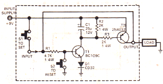
Parts list
Power circuit with soft power switch
- USB lithium charger board
- USB lithium polymer battery
- Q1: 1N3906 (PNP transistor)
- Q2: PN2222 (NPN transistor)
- D6: Any small signal diode
- R1, R2: 10kΩ resistor
- R3: 4.7kΩ resistor
- C1: 10μF (probably can be different)
- C2: 100μF (probably can be smaller)
Caliper power regulator
- D4, D5: Any small signal diode
- R4: 4.7kΩ resistor
Caliper signal voltage shifter
- Q4, Q5: PN2222 (NPN transistor)
- R4, R5: 10kΩ resistor
MCU and display
- Generic Arduino Mini Pro
- I2C OLED display
Circuit Notes
Soft power switch=
- Voltage drop between Vbatt and Vout is non ideal, but Arduino still operates fine.
- Vec_q1(on) = 0.8 - 0.3V (mosfet would be much better but i don't have any with small packages)
- so Vo = 3.4 - 2.8V depending on lithium charge ie. 4.2 - 3.0V
- On button switch must be held for about a second, otherwise circuit doesn't turn on completely
- This is because C2 needs to charge
- C2 needs to be large because when MCU shutdown pin does not pull down low long enough to completely power off and ends up resetting, then MCU shutdown pin goes high again, leaving everything on. With C2 included, the MCU discharges C2 turning off Q2 and keeps it off long enough to ensure MCU is shutdown completely
- May be able to be less that 100uF, that's just what i used
Caliper voltage supply
- diodes gives a regulated voltage of about 1.1 - 1.2V, This is lower than ideal, and not a great regulator. But is good enough an causes no problems.